 The Plan Routes tool determines how a fleet of vehicles can visit a set of stops in the least amount of time.
Note:
If you do not see the Plan Routes tool in Map Viewer, contact your portal administrator. Your portal may not be configured for routing, or you may not have privileges to run the tool. Plan Routes requires the following directions and routing services:
- Vehicle Routing Problem (Asynchronous)
- Routing Utilities
For more information, see Configure utility services.
Workflow diagram

Examples
A team of four inspectors conducts daily unannounced inspections at restaurants in San Diego County. The Plan Routes tool can be used to assign restaurants and routes to each of the inspectors.
- A team of four building inspectors has a list of 30 jobsites they need to visit. Their manager uses Plan Routes to determine how she can assign jobsites to inspectors so the most inspections can be performed within 8 hours—the duration of the workday.
Usage notes
A single layer of points is used as input to represent the desired stops.
Routes can be made based on one of several travel modes. Travel modes can be configured by the administrator of your organization. The administrator can also add new travel modes or remove travel modes that are not necessary for your organization. The default distance measure will be in Miles or Kilometers, depending on the Units setting in your profile.
| Travel Mode | Description |
|---|---|
| Follows paths and roads that allow pedestrian traffic and finds solutions that optimize travel time. The walking speed is set to 5 kilometers per hour. |
| Models the movement of cars and other similar small automobiles, such as pickup trucks, and finds solutions that optimize travel distance. Travel obeys one-way roads, avoids illegal turns, and follows other rules that are specific to cars but does not discourage travel on unpaved roads. |
| Models the movement of cars and other similar small automobiles, such as pickup trucks, and finds solutions that optimize travel time. Travel obeys one-way roads, avoids illegal turns, and follows other rules that are specific to cars. When you specify a start time, dynamic travel speeds based on traffic are used where it is available. |
| Models the movement of cars and other similar small automobiles, such as pickup trucks, and finds solutions that optimize travel distance. Travel obeys one-way roads, avoids illegal turns, and follows other rules that are specific to cars. |
| Follows paths and roads that allow pedestrian traffic and finds solutions that optimize travel distance. |
| Models the movement of cars and other similar small automobiles, such as pickup trucks, and finds solutions that optimize travel time. Travel obeys one-way roads, avoids illegal turns, and follows other rules that are specific to cars but does not discourage travel on unpaved roads. When you specify a start time, dynamic travel speeds based on traffic are used where it is available. |
| Models basic truck travel by preferring designated truck routes and finds solutions that optimize travel time. Routes must obey one-way roads, avoid illegal turns, and so on. Follows rules applicable to heavy trucks. |
| Models basic truck travel by preferring designated truck routes and finds solutions that optimize travel distance. Routes must obey one-way roads, avoid illegal turns, and so on. Follows rules applicable to heavy trucks. |
Starting points can be specified using a point layer or the Draw tool. When there is only one point, all vehicles will have the same start location. When there is more than one point, the number of vehicles must match the number of points on the layer. The Route ID field is selected to identify the individual routes, vehicles, or drivers.
All routes must have the same starting time. The starting time will correspond to the local time where the start points are located.
Routes can end at one of three locations: the start location or locations, a single end location, or many end locations. All routes will return to their starting location by default. To change the end location, uncheck the Return to start check box and add one or more end locations. If all of the routes end at the same location, the location can be specified using a layer containing a single point or by adding a point to the map using the Draw tool. If multiple end locations are used, a layer with end points can be specified. The Route ID field will be used to identify the routes, vehicles, or drivers. If there are multiple starting and ending points, the route IDs must match. For more information on route starting and ending locations, see the How Plan Routes works section.
A maximum of 100 vehicles can be specified. The tool may be able to find an optimal solution with less than the maximum specified depending on the other parameters settings.
The Maximum number of stops per vehicle parameter can be used to balance the workload between vehicles. The lower the maximum number of stops per vehicle, the more equal the number of stops will be for each driver.
The Time spent at each stop parameter will be the same for all stops and should represent the expected average stop time.
The Limit the total route time per vehicle parameter can also be used to balance the workload between vehicles. The limit is 8 hours, by default, to reflect a standard work day, but the limit can be changed or removed by unchecking the check box.
The output will be a group layer containing routes showing the shortest path to each stop, stops coded with their corresponding routes, and, if any of the stops could not be reached with the given parameters, a layer of unassigned stops.
The Select barrier layers parameter can be used to specify one or more features that act as temporary restrictions when traveling on the underlying streets.
If you select Include route layers, each route from the result is also saved as a route layer. A route layer includes all the information for a particular route such as the stops assigned to the route as well as the travel directions.
If Use current map extent is checked, only the features that are visible within the current map extent will be considered in the analysis. If unchecked, all features in the input layer will be considered, even if they are outside the current map extent.
Limitations
- No more than 2,000 stops can by specified.
- No more than 100 vehicles can be routed.
- No more than 200 stops per vehicle can be specified.
- Traffic conditions are not available for travel modes in the Plan Routes tool.
- An error will occur if the tool takes more than 4 hours to execute. If this error occurs, try rerunning the analysis with fewer input features.
- You can specify up to 250 features to act as point barriers.
- If the number of street features intersected by all the line barriers exceeds 500, the tool returns an error.
- If the number of street features intersected by all the polygon barriers exceeds 2,000, the tool returns an error.
How Plan Routes works
Plan Routes versus single-vehicle routing
Most people are familiar with single-vehicle navigation, which takes a set of stops and finds the quickest route for one vehicle to visit them. Some single-vehicle navigation tools can optimally rearrange the stop order to prevent the route from backtracking on and crisscrossing itself, which ultimately minimizes the overall travel time or distance.
Plan Routes is similar, but instead of routing a single vehicle at a time, it routes many vehicles at once. Furthermore, it determines how the stops should be assigned among the various routes and the best order in which the routes should visit the stops.
Starting and ending locations
The starting and ending locations of routes, or vehicles, are as important as the locations of the stops they will visit. By knowing all these locations, the tool can assign the stops to the nearest vehicles to reduce overall travel times. In some cases, the Plan Routes tool names the output routes based on where they begin and end.
This section describes how you can specify route start and end points and how you can associate them with specific drivers or routes. You can glance over the graphics in the following subsections and read through the one with the illustrations that best portray the start and end locations of the vehicles you are routing.
Several parameters can be used in combination to set the start and end points. To briefly introduce them, they are shown below with a short description of how they are relevant. These parameters are referenced in more detail in the subsections that follow.
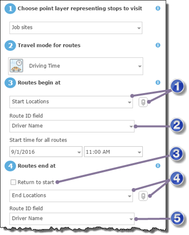
| Parameter | Description |
|---|---|
| This parameter is always required. What is important to know when setting values for the other parameters listed here, is whether you provide one or many starting points. You can define a layer with one or more points, or you can define exactly one point using the interactive editing tool. |
| This parameter appears and is relevant only when more than one starting location is specified. It can be a route number, the driver's name, or some other unique name. |
| Check Return to start if you want routes to end where they began; uncheck it if the routes end elsewhere. You also need to provide one or more ending locations if Return to start is unchecked. |
| This parameter is enabled and required when Return to start is unchecked. You can define a layer with one or more points, or you can define exactly one point using the interactive editing tool. |
| This is required when Return to start is unchecked and a layer with more than one point is specified as the ending location. The ID field can be a route number, the driver's name, or some other unique name. |
One starting point and returning to start
The most common problem to set up is one where all routes start and end at the same location. A charitable organization seeking to efficiently deliver donations to people in need parks its delivery vans at a single warehouse. On delivery days, volunteers load the vans, which then fan out to various stops to deliver the packages. The vans return to the warehouse after they complete their deliveries.
The start and end locations are set up in the following way:
- Start layer—The starting layer should have one point only, which can be specified interactively on the map or by choosing a layer with one point.
- Return to start—Checked.
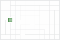
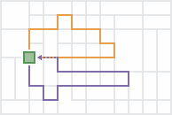
The output routes start and end at the same, single location.
One starting point and one ending point
Sometimes all routes start at one location and end at another. For instance, when planning routes for several passenger vans that will leave a depot, pick up spectators from their homes, and take them to an event, such as a concert, the depot is specified as the single starting location, and the venue of the event becomes the single ending location.
The start and end locations are set up in the following way:
- Start layer—The starting layer should have one point only (for example, the depot where the vans are parked), which can be specified interactively on the map or by choosing a layer with one point.
- Return to start—Unchecked.
- End layer—The ending layer should have one point only (for example, the event where the passengers are dropped off), which can be specified interactively on the map or by choosing a layer with one point.
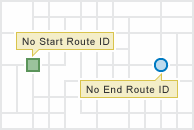
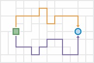
The output routes start at one location and end at another.
Because all drivers start and end at the same two locations, it is assumed any driver can drive any route, so the output routes are given names such as Route 1 and Route 2.
Many starting points and returning to start
For this problem type, each route starts from a unique point, visits its assigned stops, and finishes at the place where it began. For example, inspectors may start the day at their homes, go to various inspection sites, and return home at the end of the day.
The start and end locations are set up in the following way:
- Start layer—Include multiple points in this layer: one for each starting location (for example, a point represents an inspector's home). Note that each route is always assigned its own starting point for this problem type. If a subset of routes start at the same location, add their starting points next to or on top of each other to ensure each route has its own corresponding starting location.
- Start layer ID field—Choose the ID field for this parameter. The start layer must have a field that uniquely identifies the routes or drivers. It can be a route number, the driver's name, or some other unique name.
- Return to start—Checked.
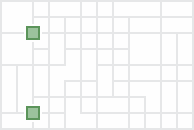
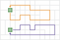
The output routes start at multiple locations and end at their starting locations.
Since the routes and their drivers start at unique locations, the ID field of the start layer must be specified. The output route names are automatically generated to be the same as the values in the ID field so the routes can be assigned and delivered to the appropriate drivers.
Many starting points and one ending point
Each route starts from a unique point, visits its assigned stops, and converges with the other routes at a single ending location for this problem type. For instance, school bus drivers in a rural school district park their buses at their homes at night. In the morning, they start their routes from home, pick up students, and drop them off at one school.
The start and end locations are set up in the following way:
- Start layer—Include multiple points in this layer: one for each starting location (for example, one point on the home of each bus driver). Note that each route is always assigned its own starting point for this problem type. If a subset of routes starts at the same location, add their starting points next to or on top of each other to ensure each route has its own corresponding starting location.
- Start layer ID field—Choose the ID field for this parameter. The start layer must have a field that uniquely identifies the routes or drivers. It can be a route number, the driver's name, or some other unique name.
- Return to start—Unchecked.
- End layer—Include one point representing the ending location (for example, the school).
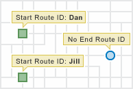
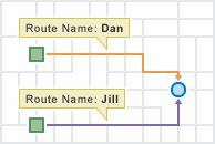
The output routes start at multiple locations and end at one location.
Since the routes and their drivers start at unique locations, the start layer has many points, and the start layer ID field property is visible and must be specified. The output route names are automatically generated to be the same as the values of the ID field so the routes can be assigned and delivered to the appropriate drivers.
One starting point to many ending points
In the one-to-many problem type, all routes start from one point, visit their assigned stops, and end at unique locations. For a utility company that needs to hang shutoff warning tags on the doors of delinquent customers, employees are offered extra pay to hang the tags on their way home from work. The employees who accept the task pick up the tags from the central office, drive to various stops to hang the tags, and end their routes at their own homes.
The start and end locations are set up in the following way:
- Start layer—The starting layer should have one point only (for example, the central office), which can be specified interactively on the map or by choosing a layer with one point.
- Return to start—Unchecked.
- End layer—Include multiple points in this layer: one for each ending location (for example, the employees' homes). Note that each route is always assigned its own ending point for this problem type. If a subset of routes ends at the same location, add their ending points next to or on top of each other to ensure each route has its own corresponding ending location.
- End layer ID field—Choose the ID field for this parameter. The end layer must have a field that uniquely identifies the routes or drivers. It can be a route number, the driver's name, or some other unique name.
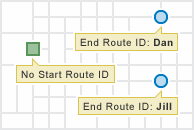
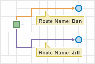
The output routes start at one location and end at multiple locations.
Since the routes and their drivers end at unique locations, the end layer has many points, and the end layer ID field property is visible and must be specified. The output route names are automatically generated to be the same as the route ID values so the routes can be assigned and delivered to the appropriate drivers.
Many starting points to many ending points
In some planning scenarios, each route has unique starting and ending locations.
The start and end locations are set up in the following way:
- Start layer—Include multiple points in this layer: one for each starting location. Note that each route is always assigned its own starting point for this problem type. If a subset of routes start at the same location, add their starting points next to or on top of each other to ensure each route has its own corresponding starting location.
- Start layer ID field—Choose the ID field for this parameter. The start layer must have a field that uniquely identifies the routes or drivers. It can be a route number, the driver's name, or some other unique name.
- Return to start—Unchecked.
- End layer—Include multiple points in this layer: one for each ending location. Note that each route is always assigned its own ending point for this problem type. If a subset of routes end at the same location, add their ending points next to or on top of each other to ensure each route has its own corresponding ending location.
- End layer ID field—Choose the ID field for this parameter. The end layer must have a field that uniquely identifies the routes or drivers. It can be a route number, the driver's name, or some other unique name.
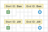
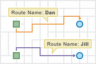
The output routes start at multiple locations and end at multiple locations.
Benefits of using Plan Routes
Plan Routes offers the following benefits:
- It simplifies the otherwise difficult job of plotting routes for a fleet of vehicles.
- It generates efficient routes, which saves time and resources for the entire organization and limits fuel usage and vehicle pollution.
- It stores the results in your portal, which makes sharing routes with drivers easier.
Route layers
Creating route layers is useful if you want to share the individual routes with other members in your organization or if you want to further modify the routes using the Directions button in Map Viewer. The route layers use the name provided for the feature layer as a prefix, and the route name generated as part of the analysis is added to create a unique name for each route layer.
Similar tools
Use Plan Routes to plan travel routes with multiple stops for a fleet of vehicles. Other tools may be useful in solving similar but slightly different problems.
Map Viewer analysis tools
If you are trying to measure the time or distance between pairs of points, use Connect Origins to Destinations.
ArcGIS Pro analysis tools
The Plan Routes tool performs a similar function to the Vehicle routing problem solver in ArcGIS Network Analyst extension.


