Note:
Analysis tools are available in Map Viewer, the modern map-making tool in ArcGIS Enterprise. To learn more, see Perform analysis (Map Viewer).
Licensing
The administrator of your organization must configure ArcGIS Enterprise for raster analytics for you to perform raster analysis. Additionally, you need the following privileges:
- Create, update and delete content
- Publish image services
If the raster analysis tools are not available, check with your organization administrator to determine whether raster analysis is configured, and confirm that you have sufficient privileges.
Access the tools
To access and use raster analysis tools in Map Viewer Classic, follow these steps:
- Open a web map containing the imagery layer or layers you want to analyze in Map Viewer Classic.
- Click the Analysis button
 on the map menu bar.
 - In the Perform Analysis pane, click Raster Analysis.
Note:
If the Analysis button or the Raster Analysis tab do not appear in Map Viewer Classic, contact your organization administrator. Your organization may not be configured with raster analytics, or you may not have privileges to run the tools. If you do not have the permissions required for the tools, they will not be visible.
Explore the Raster Analysis pane
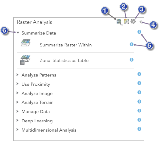
The Raster Analysis pane is illustrated below. This pane contains a number of categories, and each category contains tools. To view the tools in a category, click the expand or collapse button on the left side of the category.

The numbers in the following table correspond to the numbers in the image above:
| UI item | Description |
|---|---|
 | Open the Raster Function Editor window. For details, see Raster Function Editor. |
 | Open the Browse Raster Function Templates and Custom Web Tools window. For details, see raster functions. |
 | Open the Analysis Environments dialog box. |
 | Return to the Perform Analysis pane. |
 | Get help about the category. |
 | Expand the category to view the tools it contains. |
Use the analysis environments
Use the Analysis Environments button  to access the raster and imagery processing environments that apply to all raster analysis tools. When you open the Analysis Environments window from the Raster Analysis pane, you can modify the settings for the output coordinate system, processing extent, snap raster, cell size, and mask.
The following table describes the options in the Analysis Environments window:
| Analysis Environment options | Description |
|---|---|
| Output coordinate system | Specifies the coordinate system of the result imagery layer. The following options are available:
|
| Extent | Specifies the extent or boundary that will be used during the analysis process. All pixels or cells that are completely within or that intersect the specified extent will be used in the analysis. The following options are available:
|
| Snap Raster | Adjusts the extent of the output raster layer so it matches the cell alignment of the specified Snap Raster layer. |
| Cell size | Specifies the cell size or resolution that will be used to create the output raster layer in a raster analysis. The default output resolution is determined by the largest cell size of the input raster layer. The following options are available:
|
| Mask | The layer that will be used to define the area of interest for the analysis. Only those cells that fall within the analysis mask will be considered in the analysis operation.
|
When you open the Analysis Environments window from a raster analysis tool pane, you may see additional analysis environments. Some raster analysis tools honor several of the analysis environments listed in the table below. Because not all tools honor all the environments, they are accessed from the individual tools instead of from the Raster Analysis pane.
| Analysis Environment options | Description |
|---|---|
| Resampling method | Specifies how pixel values will be interpolated when transforming a raster dataset. This environment is used when the input and output do not line up, when the pixel size changes, when the data is shifted, or a combination of these situations. The following options are available:
|
| Processor type | Specifies whether the analysis will be run using the CPU or GPU. If the Processor type environment is empty, the tool uses CPU to process the data. The following options are available:
|
| Recycle interval of processing workers | The number of image sections that will be processed before restarting worker processes to prevent potential failures in long-running processes. The default value is 0. |
| Parallel processing factor | The number of raster processing service instances that can be used for processing the data. If the tool doesn't honor the Processor type environment, or if the Processor type environment is set to CPU, the Parallel processing factor environment controls raster processing CPU service instances. If the Processor type environment is set to GPU, the Parallel processing factor environment controls the number of raster processing GPU instances. By setting the Parallel processing factor value, you can request the number of parallel workers that the raster analytics image server uses to process one raster analysis task. However, if the total number of parallel processes exceeds the maximum number of raster processing (CPU or GPU) service instances, the additional parallel processes will be queued. If no Parallel processing factor value is specified, which is the default, the tool will use 80 percent of the maximum number of raster processing service instances. Either an integer number or a percentage can be provided as the parallel processing factor. |
| Number of retries on failures | The number of retries the same worker process will attempt when there is random failure processing a particular job. The default value is 0. |
Work with a tool pane
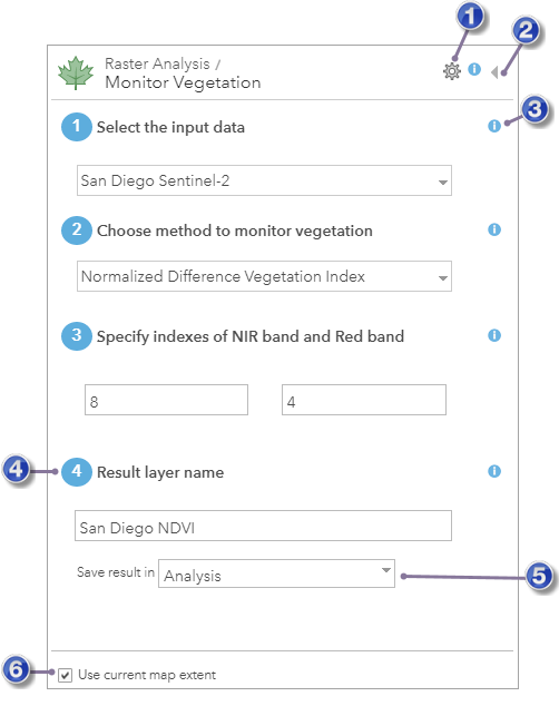
To open a raster analysis tool pane, click the tool button. This opens the tool's pane as illustrated below with the Monitor Vegetation tool.

The numbers in the following table correspond to the numbers in the image above:
 | Open the Analysis Environments dialog box. |
 | Close the tool pane without running the analysis and return to the Raster Analysis pane. |
 | Get help about a parameter. |
 | The result of running the analysis is saved to Content using this name. |
 | Specify a folder in Content where the result will be saved. |
 | If checked, only the data visible in the current map will be analyzed. |
Each tool has a different set of parameters. You can view help for a parameter by clicking the help button next to the parameter as illustrated above. All tools have a Result layer name parameter where the results of running the analysis are written. You can change this name or use the default value.
Use current map extent
It is recommended that you always check Use current map extent and that you zoom in to the area you want analyzed. Doing so limits the amount of imagery or raster pixels the tool will include when performing analysis. If you uncheck Use current map extent, the entire input imagery layer will potentially be analyzed.
 and choose from a list of known coordinate systems, or provide the spatial reference WKID in the text box.