The Elevation Profile tool  within Scene tools
  allows you to generate an elevation profile along a line. You can create an elevation profile the following ways:
- Click New Profile to draw a line over the terrain.
- Click Select Line to select an existing line feature.
Create a profile by drawing a line
You can draw a line over the terrain, buildings, integrated mesh, and features with 3D styles to view their elevation profiles.
To draw a line and generate a profile, do the following:
- Click Scene tools
 to access the Elevation Profile tool
  .
. - Click the Elevation Profile tool.
- In the scene, click to start a line and continue clicking to create additional segments.
- Double-click or click Done to finish drawing the line.
The Elevation Profile tool displays an elevation profile chart with statistics. You can interact with the chart to display more information.
- If necessary, you can move or edit the line horizontally with the handles, and the elevation profile chart dynamically changes.
- Drag the large orange disc to move the line.
- Drag the line handles to move individual vertices or create vertices in the center of segments.
- Click New Profile to draw a new line.
Create a profile by selecting a line
You can view the elevation profiles of existing lines with 2D or 3D styles in your scene.
To generate a profile of an existing line, do the following:
- Click Scene tools
 to access the Elevation Profile tool
  .
. - Click the Elevation Profile tool.
- Click Select Line.
- In the scene, click an existing line to select it and generate elevation profiles.
The Elevation Profile tool displays an elevation profile chart with statistics. You can interact with the chart to display more information.
View elevation profiles
The Elevation Profile tool  displays elevation information for the drawn or selected line.
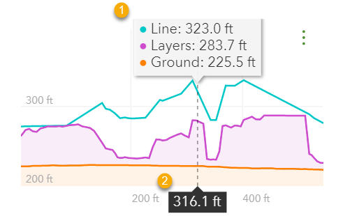
The chart displays the following types of elevation profiles:
Ground | The elevation profile of the ground or terrain. |
Layers | The elevation profile of 3D objects that are visible in the current scene view. This includes buildings, integrated mesh, and features with 3D styles. Point cloud scene layers do not generate an elevation profile. |
Line | The elevation profile of the selected line. |
Check or uncheck the check boxes to customize which elevation profiles to display.
Note:
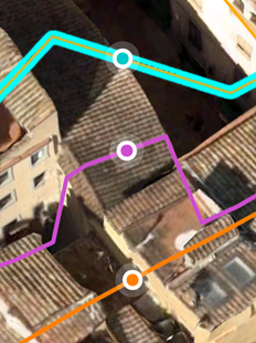
Whether a profile type generates elevation depends on the nature of the line you draw or select. In the image below, the selected line additionally crosses 3D objects, so elevation is calculated for all three types.
- The Ground profile is always generated if there is elevation where you draw the line.
- When you draw a line, the Line profile is automatically disabled.
The following image is an example of the display when you hover over the chart:


 | Elevation for the available profile types. |
 | Horizontal distance from the start of the line. |
Elevation statistics
Click the expand button  for each profile type to expand and display statistics.
Length | Length of line |
Gain | Total ascent |
Loss | Total descent |
Min | Minimum elevation of line |
Max | Maximum elevation of line |
Avg | Average elevation of line |
Max Slope | Steepest slope ascending/Steepest slope descending |
Avg Slope | Average slope ascending/Average slope descending |
Note:
- Slopes are calculated by sampling over a distance of 10 meters or more.
- The elevation profile length is a 2D length or distance along the X-axis (geodesic in WGS84 and WebMercator). The actual length is not calculated along the lines or the ground.
Change the unit
To change the unit, click the Settings button and click the Units drop-down menu.